
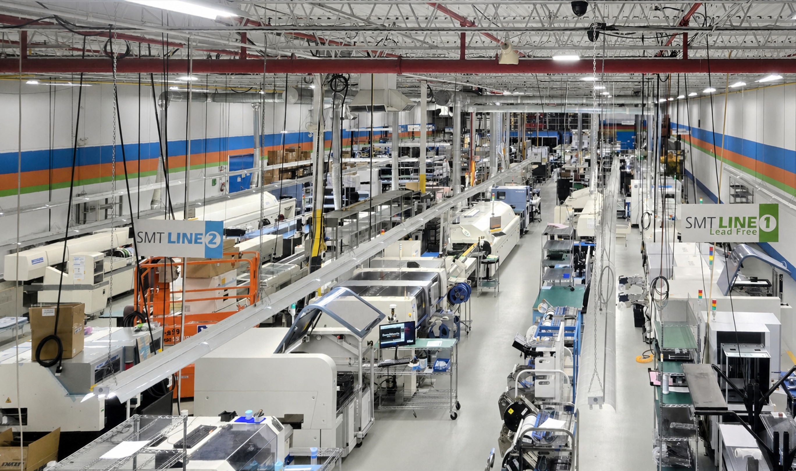
PCB Design
MIS turns product requirements into practical circuit and system designs that can move cleanly from concept through prototype and production.
Requirements and specifications
The design path begins by capturing customer requirements, applicable standards and certifications, acceptance expectations, cost targets, and the functional requirements that guide the board or system.
- Customer and product requirements
- Applicable standards and certification needs
- User-acceptance test planning
- Cost and functional requirements
- Design-readiness review
Circuit architecture and simulation
Work can range from simple transistor and discrete-component circuits to complex systems built around microprocessors. Functional blocks are modelled and analysed before they are committed to a schematic.
- System and functional block diagrams
- Feasibility and interaction analysis
- Computer simulation where appropriate
- Schematics, PCB layout, and production artwork
Component selection and continuity
Design decisions consider electrical performance alongside budget, availability, lead time, supplier continuity, and approved alternatives so the final board is not trapped by avoidable sourcing problems.
- Availability and lead-time review
- Budget and lifecycle considerations
- Catalog engineering and qualified alternatives
- Back-annotation of approved substitutions
Design for manufacturing
DFM feedback helps avoid undersized parts, unsuitable finishes, unnecessary component count, and assembly choices that increase cost, throughput time, or rework.
- Lean part-count review
- SMT and through-hole trade-offs
- Assembly cost and throughput review
- Testability and rework reduction